Devious Fab and Repair
28 X27.168 Needle Glow PCBs
Couldn't load pickup availability
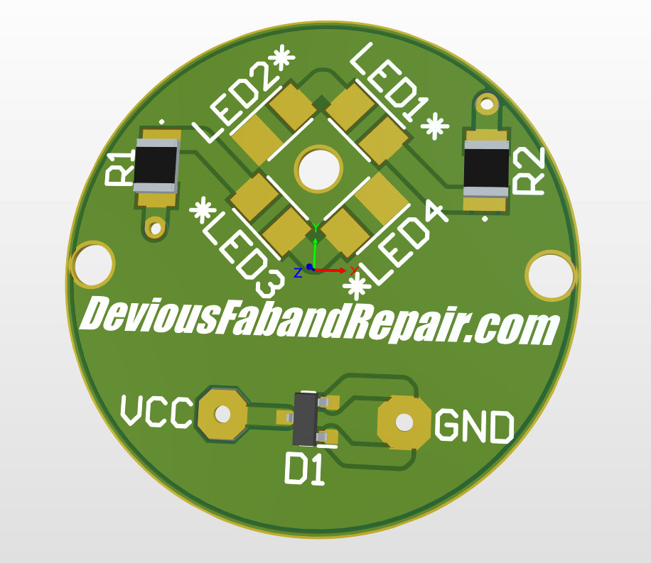
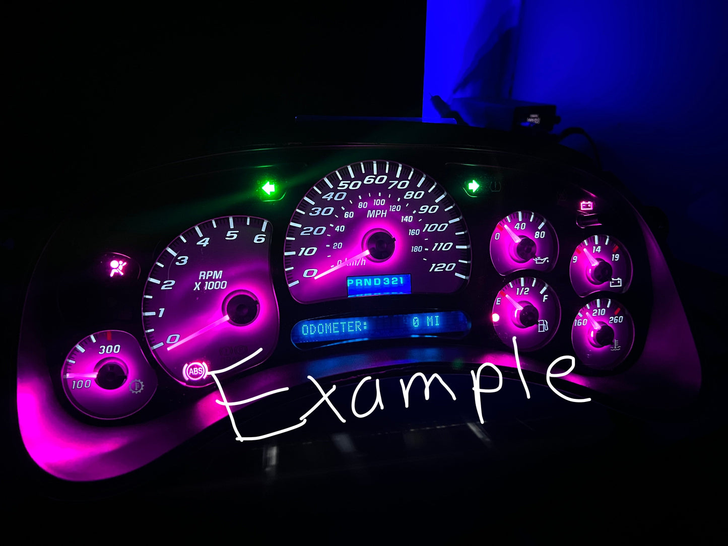
These PCBs are specifically designed to independently illuminate the needle pointers. They are being sold as a sheet of 28. Second pic shows an example of the type of needle glow you can achieve using my PCBs. The PCBs use 3528 PLCC-2 LEDs just like the warning lights found on the 03-06 gmt800 clusters and the 02-09 gmt360 clusters. (Currently finishing up assembly and install instructions)
Addressing the elephant in the room.
Somewhere in the panelization of the PCB a trace was deleted. Thankfully, it was not a major trace and can be remedied very easily with a simple solder bridge. This trace is from the bottom of R2 to the via right under. This trace is only needed for the speedo and tach applications, therefore not needed to be done on every single PCB. So sorry about this guys. I always double and triple check my work and somehow this got past me.
Resistor Sizes and Values.
The resistor package size is a 1210 in inches and 3225 in millimeters. Resistor values can be easily found using a simple equation or online calculators. I find the online calculators ten times easier and faster. Simply input a 14.7ish supply voltage, the forward voltage for the LEDs you use is usually found in the specifications for Mouser and product attributes for Digi-Key, Forward voltage is always specified in the data sheet if you cannot find the forward voltage for any reason. For the current I usually stay at 15ma for good reliability, but you can use 20ma but will be less reliable, and finally choose two for the number of LEDs. Below I will leave links to online calculators I like.
http://www.hebeiltd.com.cn/?p=zz.led.resistor.calculator
https://www.hobby-hour.com/electronics/ledcalc.php
https://www.allaboutcircuits.com/tools/led-resistor-calculator/
PCB Leads.
As for the leads, there are many different routes you can take. Considering the PCB at full tilt should theoretically only pull about .06 amps, any wire rated at that or higher should work, but I designed everything around the PCB being overbuilt. I chose 22 gauge solid core wire which is rated at 5 amps. You could order rolls/spools, or even pre cut and pre tinned jumper wires meant for breadboards. I found the longest run needed for the PCBs is 6cm. I will leave example links below.
https://www.amazon.com/gp/product/B07G2WNCN9/ref=ppx_yo_dt_b_asin_title_o08_s00?ie=UTF8&psc=1
Mounting the PCB to the motor.
For mounting the PCB to the motor any m2 screw 6-10mm in length. I would suggest wafer head or button head, countersunk might dig too much into the board, or not let the screw sit flush with the board. If you find the screw to be too small, and its like throwing a hot dog down a hall way, use a old tip for you iron and quickly run the tip into the hole, and should make the hole just small enough to thread into the motor. Here are some example amazon links.
https://www.amazon.com/gp/product/B082XXRTPK/ref=ppx_yo_dt_b_asin_title_o05_s00?ie=UTF8&th=1
Installing properly and preventing light bleed.
Because of how wide an angle the 3528 LEDs throw light (120 degrees off the top of my head) if installed without the proper modifications to the illumination lens they will bleed a lot of light. A LOT. I've tried a lot of different ways on how to counteract this but I will only be showing you the easiest way that I've found. First were going to start off with the things needed for this process You could use 5/8 inch vinyl tubing with a overall diameter of 3/4 inch or 5/8 drip tubing with a 11/16 inch overall diameter. These could be easily cut using cheap tubing cutters from amazon which I find are the perfect length when cut flush with the edge of the cutters. The next thing you'll need is a 3/4 step bit for a drill. Simply run the step bit in the already existing holes for the needles until you hit the right step all the way through for the 3/4 OD vinyl tubing or to the 11/16 step for the drip tubing. If done correctly the tubing should interference fit into the illumination lens perfectly and not need anything else.
https://www.amazon.com/gp/product/B08VW15TK8/ref=ppx_yo_dt_b_asin_title_o05_s00?ie=UTF8&psc=1
None of these links are affiliate links, these are just what I bought and what were my favorites were.